Issie (Interactive Schematic Simulator and Integrated Editor) is a very easy to use and capable hierarchical block schematic based digital logic editor and simulator, originally made for the 1st year undergraduate Digital Electronics and Computer Architecture module at the Department of Electronic and Electrical Engineering, Imperial College London, by 3rd year students at the same institution.
Issie has been well tested on designs with up to 15,000 schematic components. We expect it to be reasonably performant on much larger designs as well. The simulation speed is approximately 2000 component-clocks per ms. Thus a circuit with 1000 components would run at 2000 clocks per second. Issie creates fully synchronous circuits with a single clock: logic with asynchronous loops is currently not supported.
Issie is coded in F# transpiled to Javascript by FABLE, and uses a pure F# drawing library.
Contents
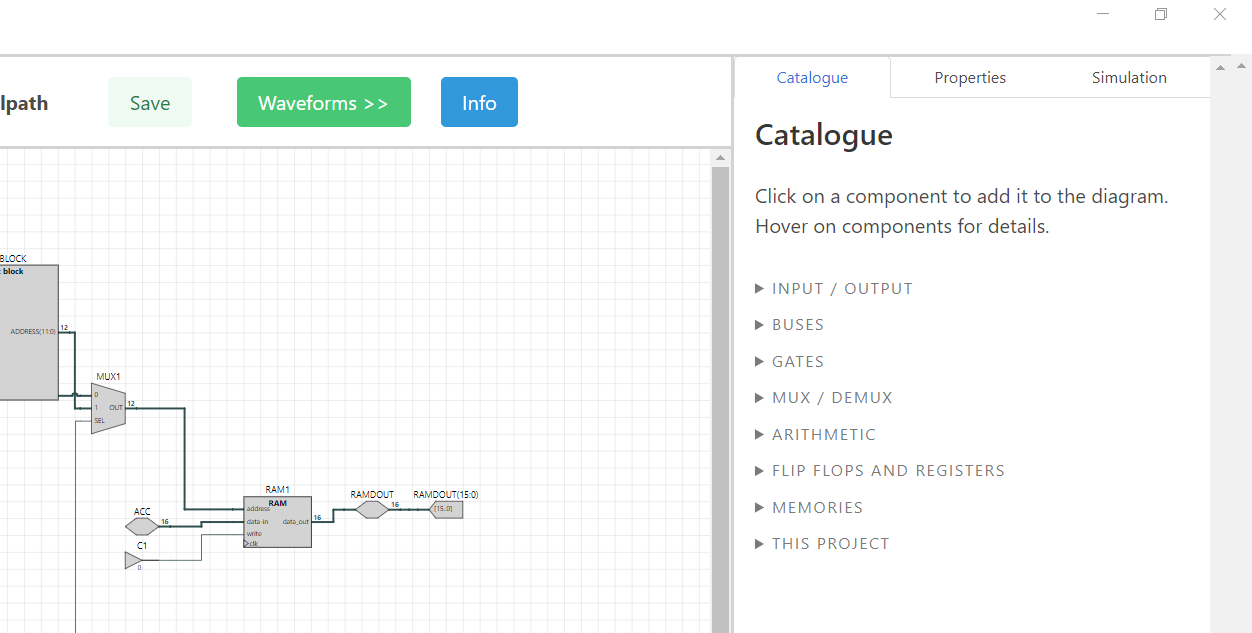
ISSIE has an extensive and complete library of components available in the 'Catalogue' menu. Components include low-level gates and flipflops as well as larger blocks: RAMs, ROMs, n-bit registers and adders. The lack of HDL-based combinational logic is partly filled by special components: Bus Select (extracts a bit-field), Bus Compare (decodes a min-term of a bus). Components defined as Verilog combinational logic are a likely future addition.
Viewer components are used to (optionally) view simulation waveforms of nodes on subsheets. Wire label components allow any number of nodes on one design sheet to be connected without visible wires.
ISSIE schematic component ports are connected using drag-and-drop: each connection represents a wire or bus. ISSIE has two methods of routing wires: Auto-routing and Manual-routing. Wires will all start out as Auto-routed, which means that the wire's path is created automatically by the program. This path will update when moving any connected components. ISSIE also allows for manual routing, where the user may manipulate segments of the wire as desired to make the circuit more readable. Effort has been put into making this functionality intuitive, with automatic reversion to auto-routing when wire topology changes, and auto-routing of endpoints when parts of a wire are manually routed.
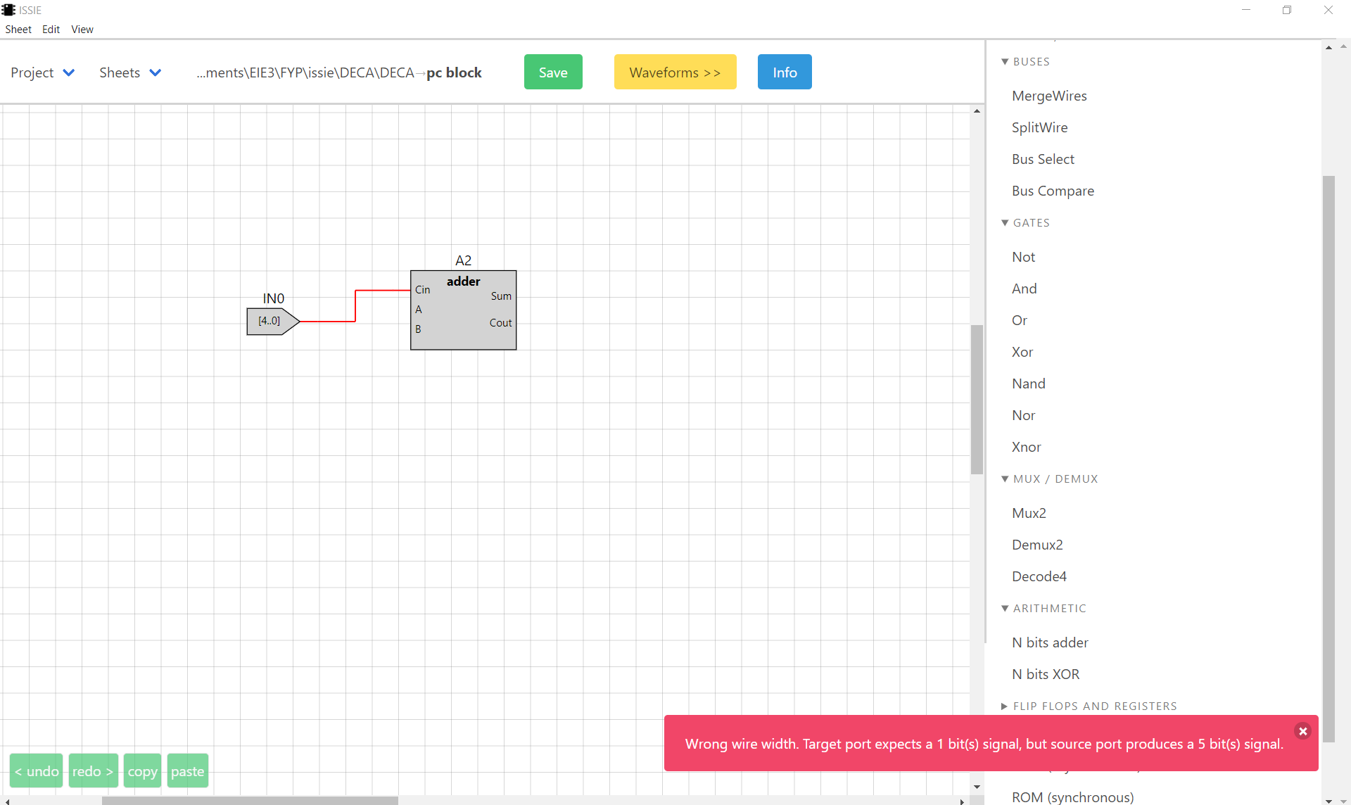
Wires will automatically be created the correct width using a width inference algorithm. Wires connecting two ports of incompatible widths will be highlighted red and an error message shown, as will multiply driven wires. Additional sanity checks (e.g. for combinational loops, or unconnected ports) are made before simulation with errors highlighted visually.
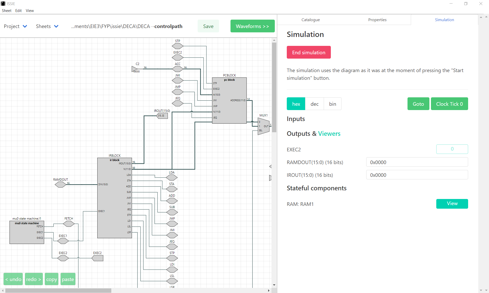
ISSIE includes two simulations in order to inspect and test circuit schematics: The step simulator, and waveform simulator. This allows users to visualise the information in different ways to best suit their needs and understanding.
Step Simulation allows the user to 'step' or cycle through each clock tick, and view the current design sheet's Output and Viewer component information. It also allows users to view how the state changes in stateful components such as RAM.
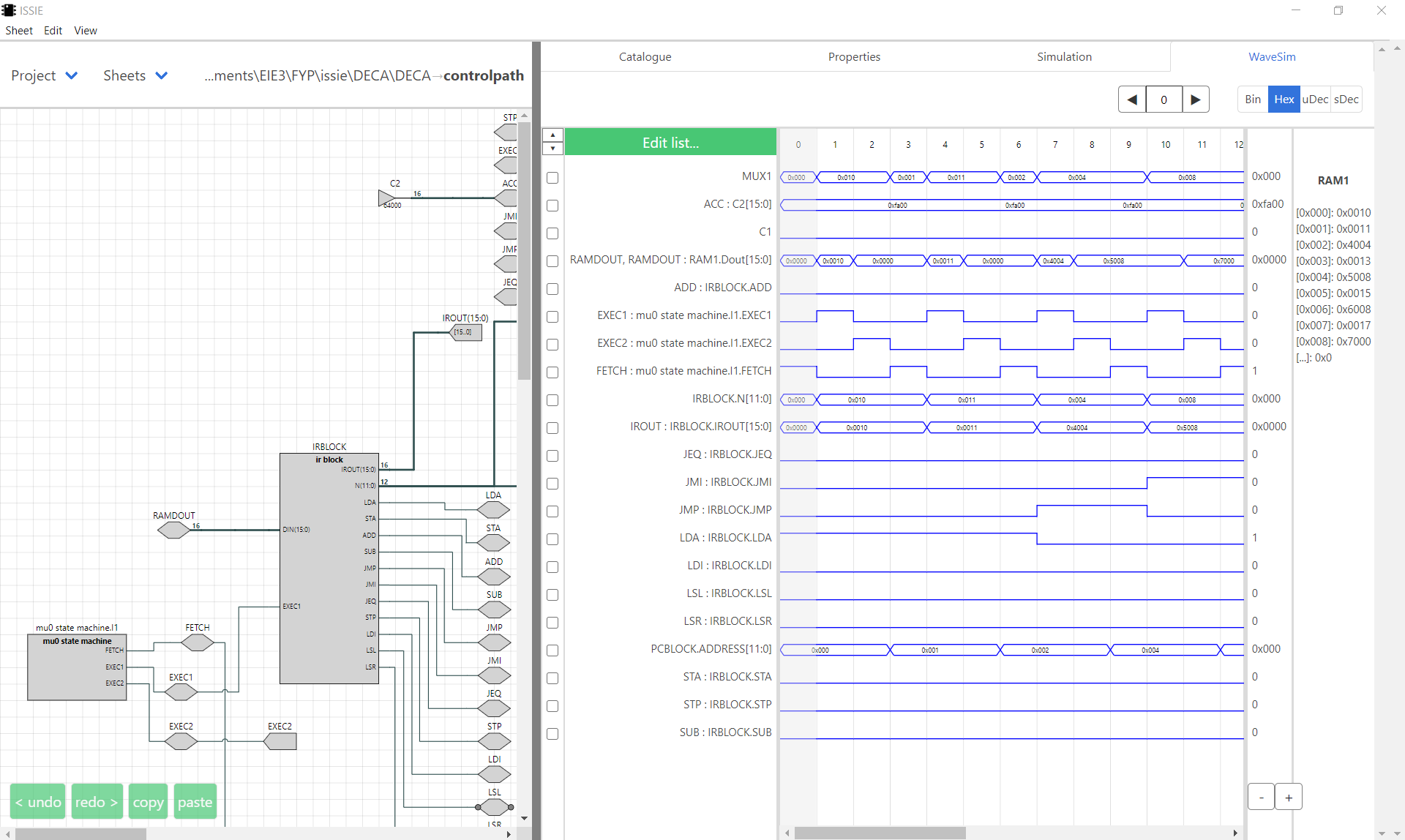
Waveform Simulation allows the user to see the values in each selected connected circuit element (Netlist) over time as a waveform. The waveform simulator allows users to move waveforms up/down in the list to make the simulation more readable. Users may cycle through the simulator using the arrows to directly go to a specific clock cycle. Alternatively there is a scrollbar for the Waveform simulator that will automatically lengthen the simulation once the end is reached. The values in the waveform simulator can be viewed in various formats: binary, hexadecimal, unsigned decimal and signed decimal. The Waveform Simulator also features a draggable sidebar to partition screen space dynamically between waveforms and circuit.
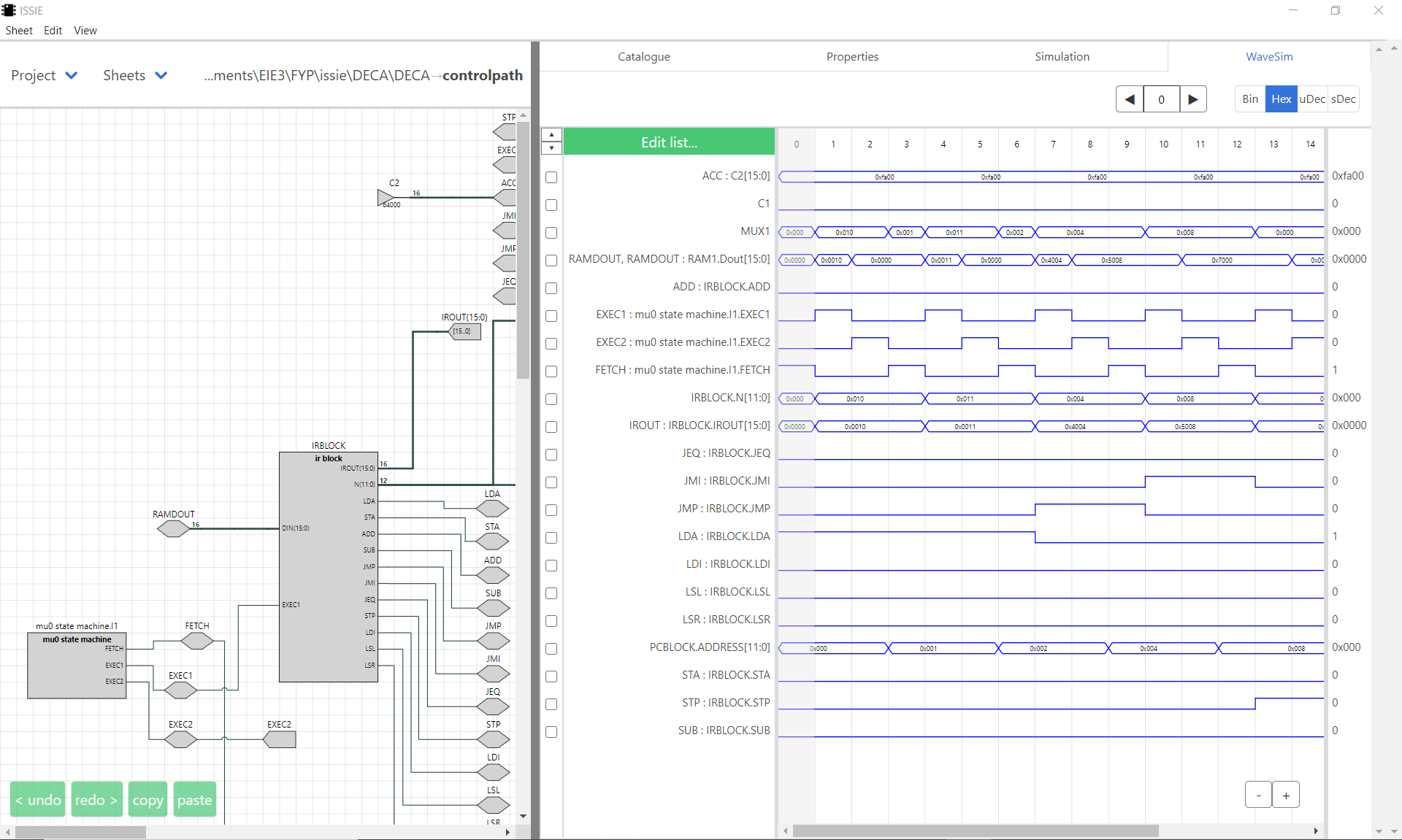
Waveform Simulation also allows for the simulation and contents viewing of memory components such as RAM.
Users may convert their ISSIE schematic design into a Verilog file using the 'Write design as verilog' option found in the header bar of the application. This allows great flexibility as ISSIE designs may be used in more complex design tools and other programs that use Verilog; allowing ISSIE to be used as a top-level design that can be further developed if needed. Verilog output for simulation or synthesis is documented as part of the Verilog write process, this includes links to a [YoSys](http://bygone.clairexen.net/yosys/download.html) workflow for synthesis on FPGAs. Imperial College users can download a pre-installed VM for this workflow, the VHDL output is standalone and should work with other synthesis methods.
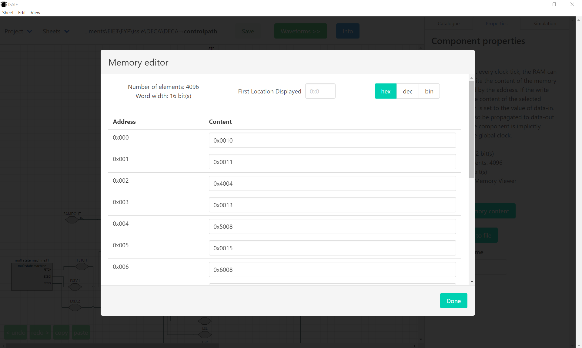
ISSIE allows users to directly edit the contents of Memory components, for more versitility and ease of use. Memory contents can also be exported and imported via .ram files.
- Marco Selvatici for the 8K lines of base code written for his 3rd year BEng FYP
- Edoardo Santi for work improving Issie over Summer 2020.
- High Level Programming 2020 cohort for providing the base code of the draw block
- Jo Merrick for work improving ISSIE for her 3rd year BEng Project
- Dr Tom Clarke for his continued work maintaining and improving ISSIE throughout
- All 2020/2021 1st year undergraduate students of the EEE department, Imperial College London, for acting as unpaid beta-testers!