mirror of
https://github.com/supleed2/ELEC50003-P1-CW.git
synced 2024-11-10 01:35:50 +00:00
101 lines
7.3 KiB
Markdown
101 lines
7.3 KiB
Markdown
|
|
# Getting started: FPGA starter project
|
||
|
|
|
||
|
|
## Running Quartus on EEE Department servers
|
||
|
|
|
||
|
|
You can compile your FPGA project on the EEE department application servers. The servers are powerful and can compile projects quickly, but you might find the graphical interface to be laggy and hard to use
|
||
|
|
|
||
|
|
### Log in
|
||
|
|
|
||
|
|
You'll need to start a SSH session with X window forwarding to allow you to use the graphical interface.
|
||
|
|
|
||
|
|
#### Windows
|
||
|
|
|
||
|
|
1. Install [MobaXterm software](https://mobaxterm.mobatek.net/)
|
||
|
|
2. Connect to [Imperial College VPN](https://www.imperial.ac.uk/admin-services/ict/self-service/connect-communicate/remote-access/virtual-private-network-vpn/)
|
||
|
|
3. Run MobaXterm and start a new session
|
||
|
|
4. Choose SSH, enter the hostname `ee-mill2.ee.ic.ac.uk` and your College username
|
||
|
|
5. Click OK and enter your College password when prompted
|
||
|
|
|
||
|
|
#### macOS
|
||
|
|
1. Install [XQuartz](https://www.xquartz.org/)
|
||
|
|
2. Start a terminal
|
||
|
|
3. Start an SSH session with `ssh -X <username>@ee-mill2.ee.ic.ac.uk`
|
||
|
|
|
||
|
|
Once you have logged in, test window forwarding by running `gedit &`. You should see a text editor window.
|
||
|
|
|
||
|
|
### Running Quartus
|
||
|
|
|
||
|
|
The servers contain different versions of Quartus. You'll need to use Quartus 16.0. First, set up the environment variables for this version of Quartus by running:
|
||
|
|
|
||
|
|
export ALTERAPATH="/usr/local/altera/16.0/"
|
||
|
|
source /usr/local/altera/.settings64.sh
|
||
|
|
|
||
|
|
Then run Quartus with:
|
||
|
|
`quartus &`
|
||
|
|
|
||
|
|
### Build the starter project
|
||
|
|
|
||
|
|
Clone the starter project to your nfshome network drive:
|
||
|
|
`cd ~/nfshome`
|
||
|
|
`git clone git@github.com:edstott/EEE2Rover.git`
|
||
|
|
|
||
|
|
`nfshome` is a network drive similar to your main College home directory (H:), which is mounted at `~/homedir`. However, Quartus doesn't work with projects stored in your home directory so you must use nfshome. You can access nfshome from other devices by mapping the network location `\\icnfs-ee.cc.ic.ac.uk\<username>`
|
||
|
|
|
||
|
|
Open the project in Quartus at `~/nfshome/EEE2Rover/DE10_LITE_D8M_VIP_16/DE10_LITE_D8M_VIP_16.qpf`
|
||
|
|
Run a full compilation
|
||
|
|
|
||
|
|
### Download the bitstream to the FPGA
|
||
|
|
|
||
|
|
Install the camera module on the DE10-Lite FPGA board. Connect the FPGA to your computer with the USB cable and run the Quartus programming utlity. You will need Quartus Lite installed locally or in a virtual machine, like you used for the FPGA lab work. You can run the programmer utlity independently of the Quartus IDE by running the executable `quartus_pgmw`
|
||
|
|
|
||
|
|
#### Method 1: Access bitstream file from programmer
|
||
|
|
1. Copy the generated file `~/nfshome/EEE2Rover/DE10_LITE_D8M_VIP_16/output_files/DE10_LITE_D8M_VIP_16_time_limited.sof` to your local computer or virtual machine, or map the nfshome directory so it can be accessed from the file system.
|
||
|
|
2. In the Programmer window, select the correct hardware device and autodetect the JTAG chain.
|
||
|
|
3. Assign the .sof file to the 10M50DA device
|
||
|
|
4. Check 'Program/Configure'
|
||
|
|
5. Click 'Start'
|
||
|
|
|
||
|
|
#### Method 2: Connect to programmer using JTAG server
|
||
|
|
1. In the Programmer window, select 'Hardware Setup', switch to the tab for 'JTAG settings' and click 'Configure Local JTAG Server'
|
||
|
|
2. Enable the server and enter a password. It can be anything.
|
||
|
|
3. Click 'OK' and close the Hardware Setup window.
|
||
|
|
4. Connect the computer or virtual machine running the Programmer to the Imperial College VPN
|
||
|
|
5. Find the IP address of the computer's VPN interface. Run `ipconfig` in Windows or `ip addr` in Linux. Look for an IP address under an entry like `PPP adapter Imperial College` - the exact name may depend on how you named the VPN connection.
|
||
|
|
6. Run the Programmer on the departmental server by clicking the programmer button in Quartus IDE or running `quartus_pgmw`.
|
||
|
|
7. Select 'Hardware Setup', switch to the tab for 'JTAG settings'. Click 'Add Server' and enter the VPN IP address of the computer connected to the FPGA. Use the password you set in step 2.
|
||
|
|
8. You should now be able to access the FPGA directly from the programmer running on the departmental server. Configure the FPGA using steps 2-5 of Method 1.
|
||
|
|
9. The JTAG server on the FPGA-connected computer does not require the Programmer tool to be running once it is set up. However, you may need to start and enable the jtag server using `jtagserver --start` and `jtagconfig --enableremote <password>`
|
||
|
|
|
||
|
|
The starter project contains IP blocks that are used under an evaluation licence. When you configure the bitstream you'll notice a window showing that you have 'unlimited' time remaining to use the bitstream. However, the FPGA will stop working if you close this window or disconnect it from the Programmer.
|
||
|
|
|
||
|
|
### Download and run the firmware
|
||
|
|
The FPGA configuration requires firmware for the NIOS II soft processor. The firmware manages configuration of the camera and its bridge device so there will be no video data until the firmware is started. Source code and a pre-built firmware binary are included in the repository.
|
||
|
|
|
||
|
|
Download the firmware to the FPGA by running:
|
||
|
|
`nios2_command_shell.sh nios2-download EEE2Rover/DE10_LITE_D8M_VIP_16/software/D8M_Camera_Test/D8M_Camera_Test.elf -c 1 -g`
|
||
|
|
`nios2_command_shell.sh` may not be found in the PATH variable for your system. It is located in the Quartus installation in `nios2eds` (`/usr/local/altera/16.0/nios2eds` on the EEE deparmental servers)
|
||
|
|
You can download the firmware from your local machine or VM, or from the departmental server once you have set up the JTAG server (Method 2 above). The parameter `-c 1` is the 'cable number' and you may need to change it if more than one item appears in the list of available hardware in the Quartus programmer. If the cable number is wrong you may get the misleading message `There is a problem with the Quartus Prime installation on your computer`.
|
||
|
|
|
||
|
|
On downloading the firmware you will see progress and status messages showing that it was successful.
|
||
|
|
|
||
|
|
### Observing the camera feed
|
||
|
|
The starter system includes a VGA video output so you can view the camera stream and any annotations you might apply for debugging purposes. Connect the 15-pin VGA port on the FPGA board to your computer using the VGA to USB adapter module. The adapter module enumerates as a camera device so you can see the video stream by opening the camera app on your computer and selecting the 'AFN_Cap' camera.
|
||
|
|
|
||
|
|
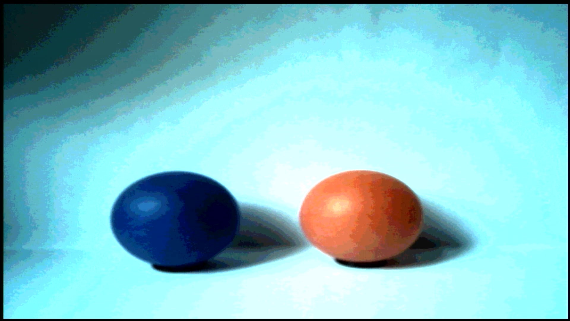
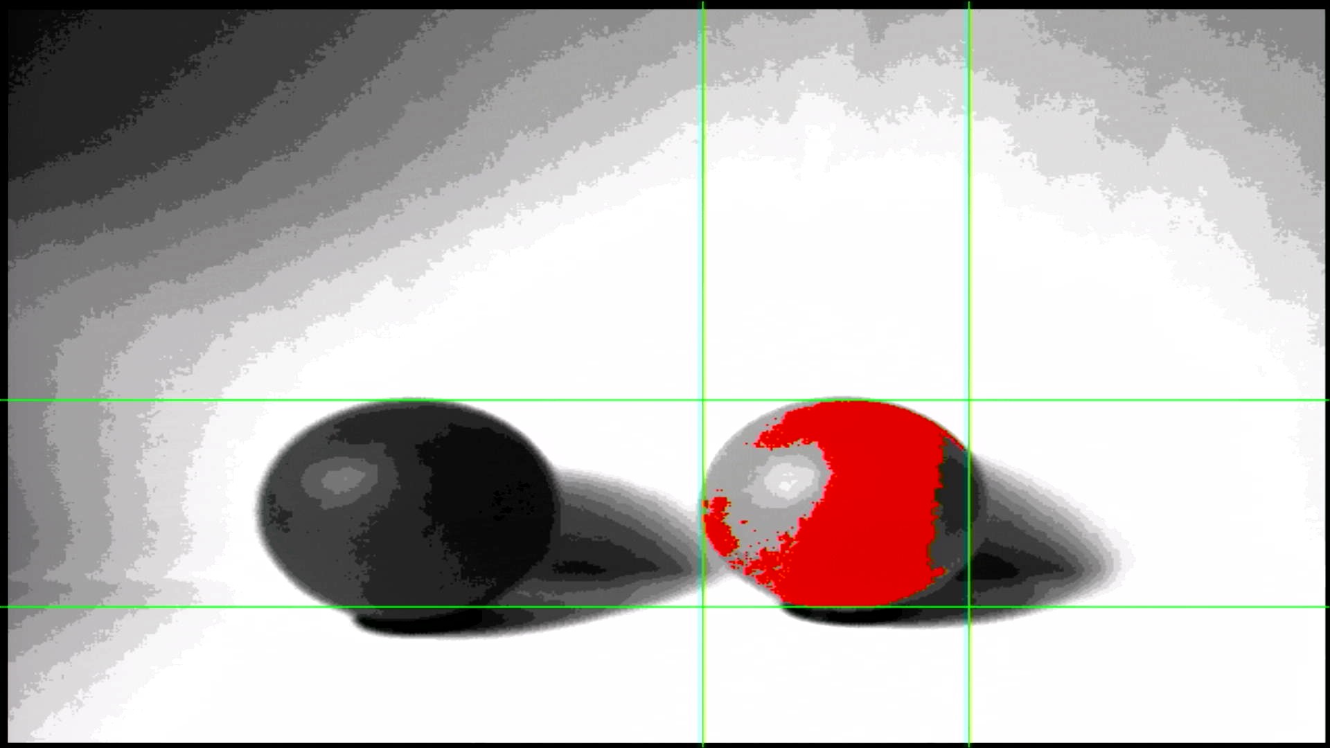
If the FPGA has the default power-on configuration (counting digits) then the video stream will show a blue Altera/Terasic splash screen. If the FPGA has been configured with the starter configuration and the firmware has been downloaded, you will see the camera feed. Toggling switch SW0 will switch between raw camera data and a basic image processor output that highlights red pixels.
|
||
|
|
|
||
|
|

|
||
|
|
*Unprocessed Image*
|
||
|
|
|
||
|
|

|
||
|
|
*Image highlighting red pixels*
|
||
|
|
|
||
|
|
The VGA output from the DE10-Lite board has only 4 bits per colour channel and you will notice the limited colour depth in the displayed video stream. The camera produces 8 bits of colour depth per channel, which means that your image processing algorithm will be able to 'see' a higher colour resolution than can be displayed on the video output.
|
||
|
|
|
||
|
|
|
||
|
|
|
||
|
|
|
||
|
|
|
||
|
|
|
||
|
|
|
||
|
|
|